Management Information Base
One problem in the management of networks is deciding how the statistics and configuration data should be represented. Each device (switch, router, host, etc.) will have different configuration requirements and internal data structures according to its implementation. Similarly, each network management tool will have different commands and management screens displaying and requiring subtly different pieces of information. Nevertheless, any two devices that perform the same function in the network (e.g., two OSPF routers) require substantially the same configuration to enable them to operate their IP-based protocols. This means all that is required is a common, standardized way to represent the data while they are moved between management station and device. The management tools are free to collect and display the information in whatever way they choose, and the devices can store the information and use it (or discard it) as they see fit.
For each protocol that it develops, the IETF produces a standard set of operational configuration and statistics information necessary for successful configuration and management of a device that runs the protocol. This information is published in separate RFCs for each protocol and constitutes a module from the global network MIB.
The MIB is an ordered, structured view of all of the information in all networks, all at the same time. This is a pretty ambitious claim that is, in fact, true only within the global uniqueness of identifiers such as IP addresses and router identifiers. The secret to meeting this aim lies in the way that data values (or objects) are given unique object identifiers (OIDs) in a hierarchical and somewhat longwinded way.
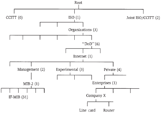
To illustrate this, consider the part of the OID tree shown in Figure below. This shows the root of the tree and the branches down as far as some individual MIB modules. As can be seen, the MIB is broken into branches according to the standards-making body. Within the ISO branch, the American Department of Defense is responsible for the Internet. So all Internet OIDs begin with the value 1.3.6.1 using dot notation to represent the OID. Standardized IETF MIB modules are assigned from the MIB-2 branch of the Management branch, but those that are still under development usually come from the Experimental branch. Another branch is designated for private use and allows enterprises (companies, network operators, research establishments, etc.) to develop their own MIB modules. So, for example, OIDs in proprietary Cisco MIB modules begin 1.3.6.1.4.1.9, where 9 has been assigned to denote Cisco.

Below these points in the OID tree come the individual MIB modules. An MIB module contains all of the configuration and reporting information for a single type of logical component. This may be a line card or router or may be a component of a protocol such as an interface as managed by the Interfaces MIB (IF-MIB) module. In other words, MIB modules are defined to manage all instances of a single type of manageable entity.
MIB modules comprise individual scalar objects and MIB tables. On a managed object (e.g., a router) the scalar objects can be thought of as global variables, and a MIB table can be thought of as an array of control blocks. Just as an implementation might need several types of control blocks, so a MIB module may include more than one table.
The scalar objects are each assigned a single object identifier within the MIB module. Thus, in the IF-MIB module documented in RFC 2863, there is an object called ifTableLastChange that records the time at which the Interface table was last changed. This object is assigned the OID 5 from within the MIB module, giving it the full OID of 1.3.6.1.2.1.31.1.5, where the penultimate 1 indicates that this is an object in the MIB.
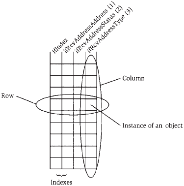
Each table is also assigned an OID within the MIB module. So, for example, the Interfaces Receive Addresses table (ifRcvAddressTable) in the IF-MIB module that is used to list all of the addresses that can be used on an interface has the value 4. Each table is made up of a series of MIB rows or entries. An entry is the equivalent of a single instantiation of a control block and is made up of a sequence of objects, each with its own object identifier. The ifRcvAddressTable contains three objects: the address itself, the current status of the address (available for use or not), and the volatility of the address on the interface assigned the OIDs 1, 2, and 3, respectively, so that the address object (ifRcvAddressAddress) has the full OID of 11.3.6.1.2.1.31.1.1.4.11, where the penultimate 1 indicates that this is an entry in the table. Thus, all of the addresses in this table form a conceptual column in the table with the same OID.
Rows in MIB tables are distinguished by indexes. Indexes are object values within the table or within some other MIB table on which this one depends. In our example of the Interfaces Receive Addresses table, there are two indexes. The primary index is the interface identifier itself, a value stored in a separate table, and the secondary index is the interface receive address in the ifRcv- AddressAddress object. Using these two indexes it is possible to select an individual row in the table and find out about a specific address on a specific interface. Alternatively, using just the primary index, and a "get next" operation, it is possible to read each of the addresses in use on a given interface. The table format is shown in Figure below.

In this tutorial:
- IP Network Management
- Choosing to Manage your Network
- Choosing a Configuration Method
- Command Line Interfaces
- Graphical User Interfaces
- Standardized Data Representations and Access
- Making the Choice
- Management Information Base
- Representing Managed Objects
- Simple Network Management Protocol
- Requests, Responses, and Notifications
- SNMP Versions and Security
- Choosing an SNMP Version
- Extensible Markup Language
- Extensibility and Domains of Applicability
- XML Remote Procedure Calls
- Simple Object Access Protocol
- XML Applicability to Network Management
- Common Object Request Broker Architecture
- Interface Definition Language
- The Architecture
- CORBA Communications
- Choosing a Configuration Protocol
- Choosing to Collect Statistics
- Policy Control
- Choosing to Apply Policy
- Policy Information Base
